Installation of Winjet Renegade Sequential Headlamps, Diode Dynamics H1 and H7 HID Bulbs, and Diode Dynamics HID Relay Harnesses.
First, thanks to Ryan (Rambodog,) who did this installation previously and whose help was extremely valuable with a myriad of questions I had.
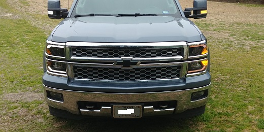
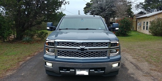
Second, one of the reasons I'm changing the headlamps out is because the OEM are not making me happy. What was on the truck was the second set of OEM in 90,000 miles and they are eroding, crazing and deteriorating again, and it's not like I travel in a big city with a lot of particulate matter in the air from pollution, or ride behind a sand truck on a daily basis. The Winjet headlamps seem to be of very high quality, and I'll get the bonus of the white LED bars to match the running lights on the front of my tow mirrors, so I'm giving them a try.
Third, I will say that my method of installation for the Relay Harnesses and HID components is probably way "over the top" and overkill, but that is the way I generally like to do things. I don't take shortcuts. In the installation of the electrical components. I used aircraft grade 2024T3 aluminum angle and "C" channel, aircraft grade Rivnuts, aircraft grade "Amphenol" terminal ends, and all stainless steel hardware.
Everything was applicably labeled, so there isn't any guesswork when/if parts have to be replaced. I gave many days of thought to placement of the components, realizing in advance there is not a great deal of room in and around the right Headlamp, due to the airbox.
Parts list: (minor hardware and electrical items omitted.)
- Winjet Renegade Headlamp Assemblies
- Quantity 2-Diode Dynamics Relay Harnesses
- Quantity 2-Diode Dynamics H1 HID Bulb Kits
- Quantity 2-Diode Dynamics H7 HID Bulb Kits
- Quantity 1-8' long red 4 gauge battery cable, cut to proper length
- Quantity 1-5' long black 4 gauge battery cable, cut to proper length
- Quantity 1-11.5" piece of Aluminum "C" channel
- Quantity 1-8" X 1.5" X 1.5" piece of Aluminum Extruded Angle
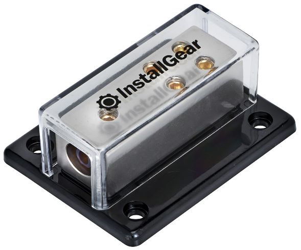
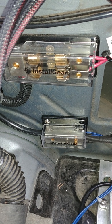
- Quantity 1-4 way power distribution block (black, to use for grounds)(InstallGear, Amazon)
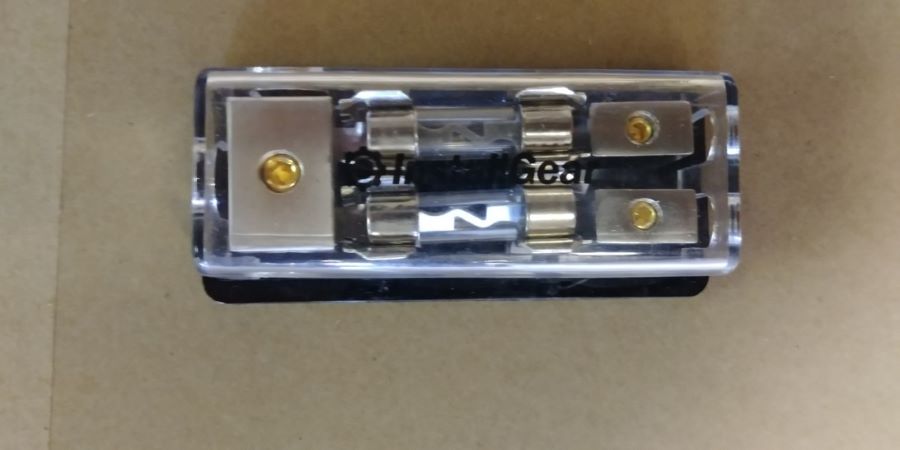
- Quantity 1-2 way fused power distribution block (black, to use for relay power)(InstallGear, Amazon)
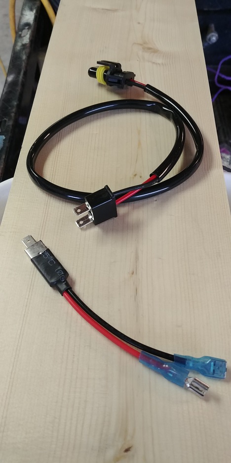
- Quantity 1-H1 Spade Adapter (Ebay)
- Quantity 1-H7 Plug Adapter (Ebay)
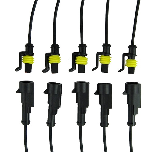
- Quantity 4 sets 16 Gauge Single Pin waterproof connectors (Amazon)
- 9006 Universal Male Plug end
Relay Harness(es) and Ballast Mounting/ Installation:
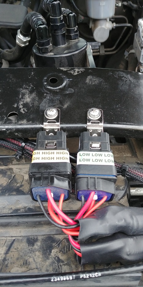
There are 2 relay harnesses. One for the Low Beams and one for the high beams. Each relay harness consists of 5 cables; Fused 12V power, Ground, 2 Ballast Cables, and a "signa/triggerl" cable. (I'll discuss later.)
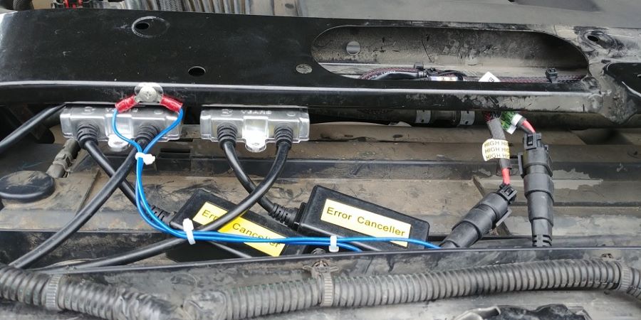
First, I mounted the two Relay/harness assemblies on the forward side of the Radiator support, left side, directly forward of the Catch Can, using 10-32 Rivnuts and stainless steel screws. The Relays face downward, so as not to interfere with the "Sight Shield" when I reinstall it. (That's what GM calls the large plastic cover.)
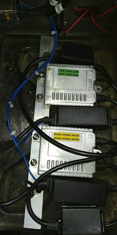
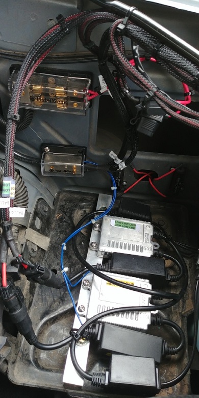
Then I mounted the two Ballasts for the Left side Headlamp onto a piece of Aluminum "C" channel with Rivnuts and stainless steel screws and mounted the assembly to the auxiliary battery tray by removing two existing bolts, match drilling the holes in the "C" channel, and inserting longer 6-1.0 X 40MM bolts. There is ample room in and around the auxiliary battery tray for all the additional ballast components.
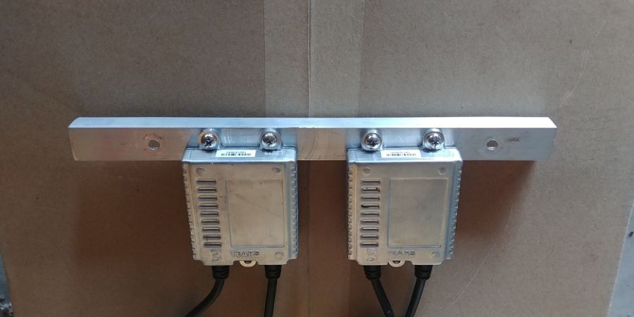
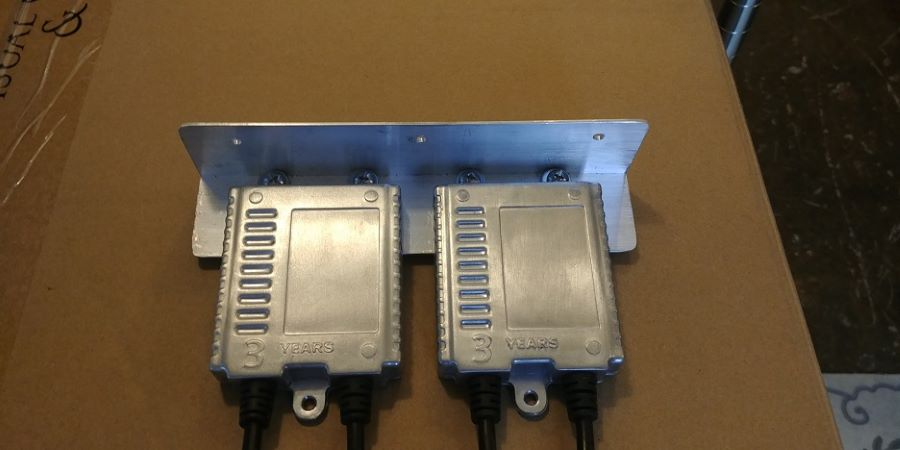
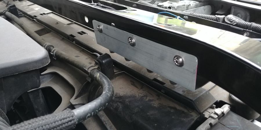
I mounted the two Ballasts for the right side Headlamp onto a piece of 1.5" X 1.5" X 8" Aluminum Angle, slid the assembly under the radiator support from the back side, clamped it tightly against the underside of the support, drilled, installed and fastened the angle with 10-32 Rivnuts and stainless steel screws.
The placement of the angle is just before the radiator support curves downward towards the right fender. There is also ample room on top of the Radiator shroud for the ballast components and wiring to reside.
Next, I ran the wire provided by Winjet, (pre-terminated,) that powers the white LED Strips from the right Headlamp "area" through the open "box" channel of the Radiator support, over to the Relay/harness assemblies to meet up with the other wiring going to the left side components and Headlamp.
Next, I ran one Ballast cable from each relay, (the long cables, although way too long for the way I did this,) through the Radiator support box channel, towards the right headlamp to plug into the Ballasts. After I had the wiring where I wanted it, everything was zip tied into place. I also created a new ground stud for the two right Headlamp Ballasts.
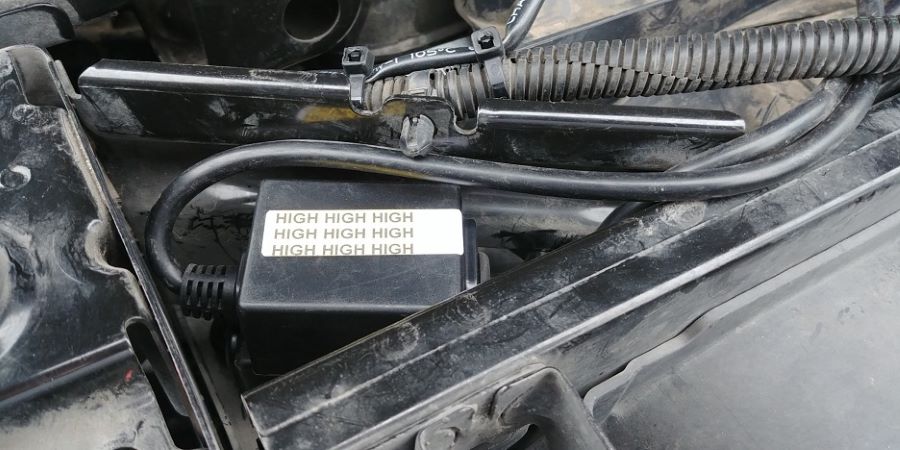
The "Error Cancellers" and all the connections stow neatly on top of the radiator shroud. In addition, just to the right of the radiator shroud the radiator support forms a small triangular "pocket" that's just perfect to stow the Canbus modules that are hard-wired into the cables going from the Ballasts to the bulbs. This required extending the cables that go directly to the bulbs about 12 inches. I made extensions using male and female 16 gauge single pin waterproof connector pigtails just spliced together.
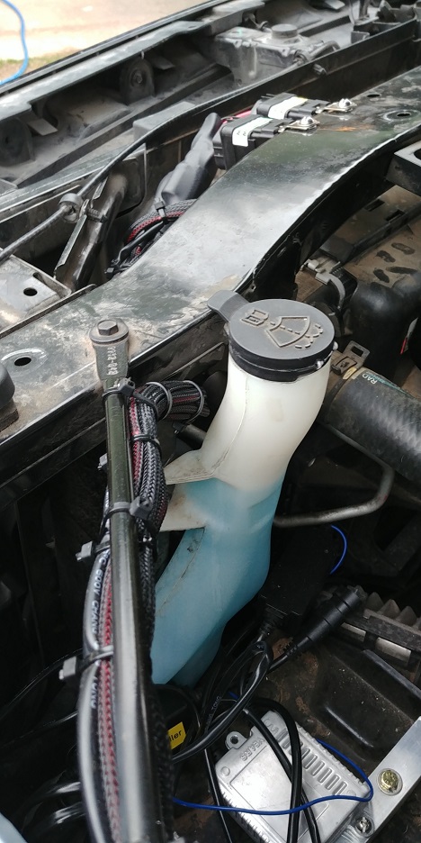
I then took the 2 "signal/trigger" cables, 2 remaining "short" ballast cables, 2 ground cables, 2 fused power cables and Winjet LED strip power wire, "combed" them into a "proper," neat wiring harness, zip tied it all together and ran it around the windshield washer reservoir, across the radiator support rod, and left it hanging, awaiting further termination.
Power and Ground
Took the 8' long red 4 gauge battery cable I purchased, covered it in split plastic wire loom, and before attaching it to the "accessory" terminal on top of the battery that currently has my Amp Power Step Power and Kicker Key Power wires, ran it across the top of the firewall, zip tied it to existing wiring harnesses, and along the left inner fender wall to where I installed a black, fused, 2-way distribution block.
Cut the wire to length, tinned the end, and installed it into the block. Then I attached the other end to the battery terminal. (Note: It's really unnecessary to have a fused terminal block, as the Relay power wires have in-line fuses, but it gave me the ability to complete part of the installation over time without having to worry about shorting anything out.)
Then I took the 5' long black 4 gauge battery cable I purchased, attached one end to the ground stud on the firewall to the right of the brake booster, ran it around the left inner fender wall, cut it to length, tinned the end, and installed it into the black 4-way power distribution block.
I finished connecting the two power wires from the relay harness to the two-way distribution block, 2 ballast cables from the relays to the ballasts, and 4 grounds. (2 from the left ballasts and 2 from the relay harnesses to the four-way distribution block,) and neatly zip tied everything into place.
Relay Signal Wiring/Headlight Housings
The reason behind having Relays is that the ballasts and the HID bulbs draw a great deal of power on start-up, so it's actually preferable to have the bulbs powered directly from the battery through a relay. Each Relay uses the bulb connector from within the Headlight housing as a "signal/trigger," to energize the Relay and provide battery power to the Ballasts and HID bulbs.
I decided to use the Left Headlight assembly to install the Signal wiring because of all the room for wiring behind it for easy access, even though I did all the "prep work" before installing the Headlights.
Instead of "cutting off and splicing" the connectors intended to plug into the bulbs within the Headlight assembly, (but now are serving as the "signal/trigger,") I found adapters on Ebay that plug directly into the Headlight housing connectors. For the H7 Low Beam Bulb the adapter used is the one with the black plug on one end, and a 9006 male plug on the other end so it mates with the "signal/trigger" harness connector.
For the H1 High Beam the adapter used is the one that looks like an oversized "spade" connector on one end, and to the other end I cut off the pre-assembled/supplied ring terminals on the adapter and added a 9006 male connector, so it mates with the "signal/trigger" relay harness connector. Shrink tubing and/or a zip tie was applied to keep the connections from vibrating loose.
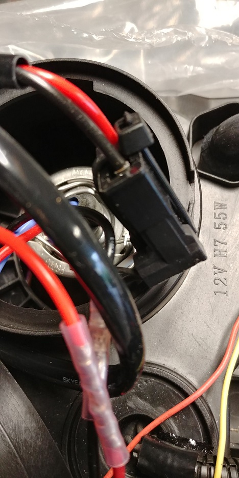
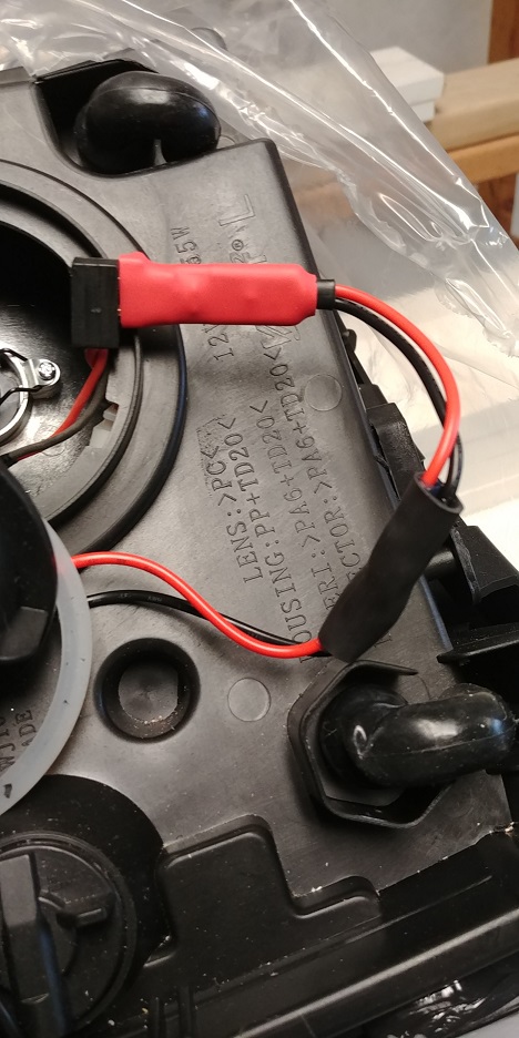
In addition, wiring the headlight assemblies requires, (per the instructions,) cutting a 1" diameter hole in the caps for a grommet with the two bulb wires and two signal wires with a "9006" male connector to pass through and connect to the ballast and signal wire harness from the relay. First, I only cut a 7/8" diameter hole in each cap.
Even though I used a precision, "aviation grade" sheet metal counterbore with a #10 pilot, anything used whether it be a spade bit, drill bit, forstner bit, router bit or punch, because of the thin brittle plastic, will have a tendency to make the hole larger than you intended, Using a 7/8" precision counterbore cutter insured a tight fit.
Second, in my installation, the signal wires in the grommet for the right headlamp high and low beam will go unused, so I cut them off, removed them from the grommet, and plugged the holes in the grommet with a little black RTV to insure a tight seal.
Last wiring step:
The last wiring step was to complete the connections for the white LED strip harness. Each headlamp assembly has a one wire "pigtail" ready to connect to the harness provided by Winjet, (see last paragraph of: Relay Harness(es) and Ballast Mounting/ Installation,) and then using a "T" Tap, this wire needs to be connected to the "parking circuit," otherwise you don't have front parking lights, because the signal lights are not "dual function" on the Winjet housings; They're just signal lights. That being the case, and the fact that you want to run the white LED strips by themselves, I tapped into the Violet/Gray wire at the left Headlight connector.
Two last worthy of note: First, is that the Winjet Assemblies use LED technology for color change on the sequential strips, but they are "old school" when it comes to the 2 signal light bulbs in each assembly. They are, and must remain incandescent, otherwise you'll get hyperflash, and the sequential strips and turn signals wont work, and adding resistors won't change that.
Second, the only problem with the installation is that at first, the sequential strips and the left side signal lights didn't work….The fix was easy. I found one pin in the headlight connector was not fully seated.
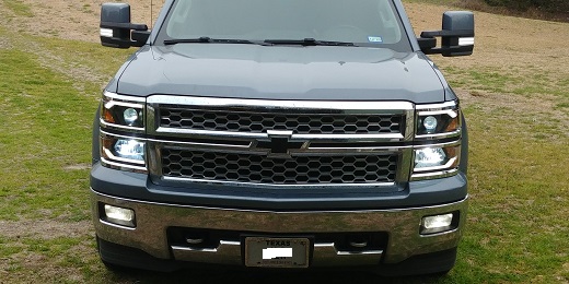
Still have to aim the headlamps, but light looks really good.
Since Winjet does a good job on their "full function" video, I didn't do one myself. Here's the link:
Story’s Author
 United States of America, Lake Whitney, Texas