Before proceeding, you will need to have your headlights baked, and the lenses removed. You can find a write up on this process here: https://ownery.com/@apolymoxic...
This can also be called "Sidemarker Switchback Mod" - I thought I would add this for search purposes.
What you'll need:
- Screwdriver
- Dremel (or some kind of precision cutting tool)
- LED switchback board (w/ TPC) - exLED Kia Optima K5 ('10~) Custom 2Way LED Front Light Reflector Kit
- White Diffuser - exLED Kia Optima K5 ('10~) Front Reflector Light Diffuser Film
- Mechanic wire
- Solder and soldering iron
- Silicon / caulk (or some kind of glue type substance - preferably clear or white - optional, but highly recommended)
I would like to point out that the above links (from exledusa.com) have some pictures that are intended as a DIY guide. But, I feel that it would be easy for someone to get confused by trying to follow pictures alone. In addition, the above guides do NOT give wiring information. So, I created this one to clear up any confusion! Also, you may get these parts elsewhere, but the parts may slightly differ (such as wire colors and small variances). However, this guide should still be able to walk you through the mod.
Step 1:
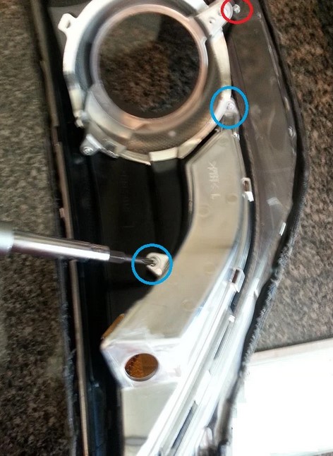
Remove the holder of the reflector. This holder is secured to a plastic portion, and that plastic portion is secured to the lens. To make the removal (and replacement) of this holder easy, remove the screw that secures the plastic portion to the lens. This screw is show in the pic below and is circled in red. After that screw has been removed, remove the two screws that hold the holder in place (shown in the pic and circled in blue).
Lift the plastic portion slightly away from the lens and then remove the holder. After removing the holder, you'll see the reason why you didn't pry the holder out of place.
Step 2:
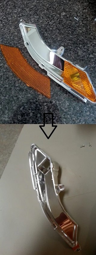
Remove the reflector from the holder. This is pretty straight forward; there are two pieces of the reflector - remove them both.
Step 3:
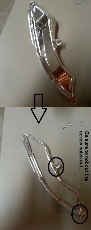
Cut out the back of the reflector (the ENTIRE back portion). This is easily achieved with a Dremel, just be sure to not over cut and break the holder. Once you remove the back, the holder is a bit flimsy... it did, after all, lose much of it's structure. You'll also want to be careful to not cut the screw holes out.
Step 4:
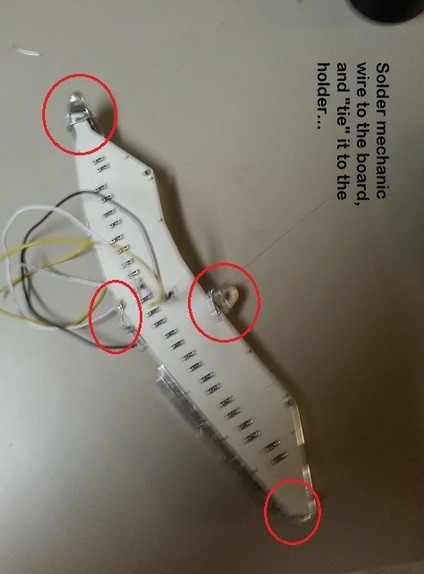
Place the board (LEDs facing inward, wires facing outward) over the hole that you just cut; make sure you attach the board to the correct side... you will attach it to side you just cut so that the board replaces the backing of the holder that you just removed. Attach the board to the holder by soldering mechanic wire to the board, and "tying" the mechanic wire to the holder. You can also solder the mechanic wire together after it's been tied.
Step 5:
Place the white diffuser over the area where the reflector and holder were. Using the soldering iron you used in the previous step, "melt" the diffuser to the plastic at a few points. Work your way from one end to the other, melting a point every couple of inches.
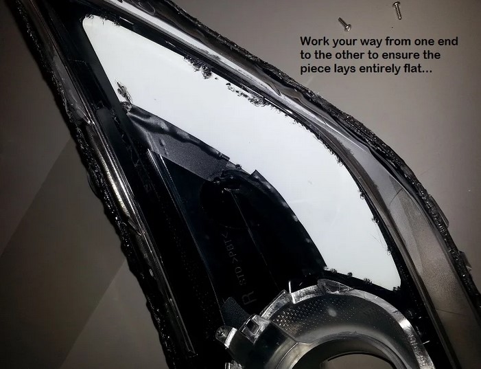
NOTE: The melting process is very quick. DO NOT hold the soldering iron on too long as it may melt all the way through the plastic. After melting a few points, I recommend using clear or white caulk and going around the edges of the diffuser to secure it in place. Allow at least 30 minutes for the silicon to set.
NOTE: The walk through on exledusa.com says to use electrical tape to secure it in place. I used a little, but I don't think it's needed if you secure it white caulk. You may want the tape if you use clear silicon or don't use any silicon at all, just to make sure no light escapes.
Step 6:
Reattach the holder (now with the LED board) to the plastic portion and lens.
Step 7:
Reattach lens to the housing, pulling the LED board wires through the hole for the old parking light bulb.
OPTIONAL NOTE: To keep a clean install, you can place the TPC module and all the wiring inside housing. To do this, secure the TPC module somewhere in the housing, connect the wires from the LED board to the TPC module "out" port (wires connect color to color), then connect the TPC module "in" port to the correct points in the housing. I believe this is:
[*=1]White from TPC to white on housing (where reflector light was)
[*=1]Black from TPC to black on housing (where reflector light was)
[*=1]Yellow from TPC to red on housing (where turn signal goes) - UNVERIFIED - Would someone please verify this for me?
I recommend doing this IF you do not plan on adding the http://www.optimaforums.com/forum/6...ifications/28602-vent-switchback-led-mod.html. I didn't do this because I didn't think of it before I closed my lights, and I was doing the vent switchback mod.
If you go this route, continue to step 8, and you are finished.
Step 8:
Close lights up (bake closed) - please refer back to http://www.optimaforums.com/fo... for help with this.
Step 9:
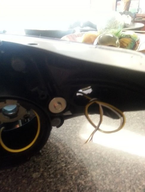
Take the holder of the old parking light bulb and remove the bulb. Create a hole in the end of this piece, then create a channel all the way down the piece (as shown in the below pic). This will allow a passage for the wires, while keeping the hole in the housing minimized. Do not seal the hole any more than this as that may hinder reopening the light.
Step 10:
IMPORTANT NOTE: This step pertains to the stock non-HID housing. I do not know the pin layout for the stock HID housing. If someone would like to send me a wiring diagram, or information on those housings, I will be glad to add it here.
Ah, the wiring! This part took me the longest time to figure out, and I ended up having to pin out the connector myself. Luckily, you don't have to because jtrade (View Profile: jtrade - Optima Forums : Kia Optima Forum) has helped out by finding these:
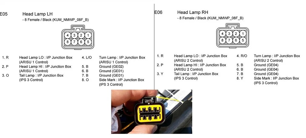
To make these lights switchback, you will need TPC modules for the LED boards. Without the TPC module, the lights will work, but the white lights will not turn off when the blinker turns on. On the TPC module "in" port, connect the following:
Black wire to ground (pin 5, 6, or 7, or you can create your own ground... I recommend using a pin. I used pin 5)
White wire to pin 3 or 8 (I used pin 3)
Yellow wire to pin 4
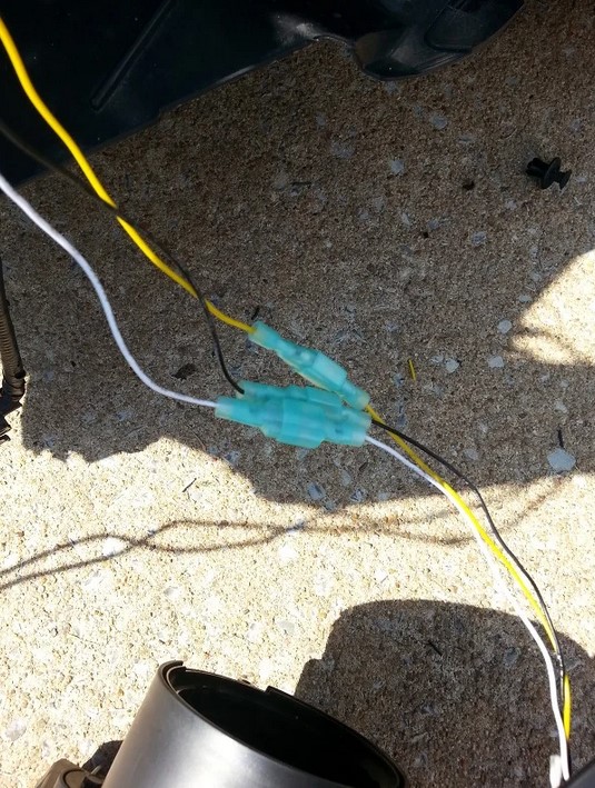
In the picture below, I have drawn a small diagram of how the wires should connect. For simplicity, I have labeled the wires (black, white, and yellow) as if they were connected to the pins I used. This diagram has a "resistor" connected to pins 4 and 5, which is used for a switchback mod on the front turn signals
Step 11:
Connect the wires from the LED board to the TPC module "out" port. I highly recommend doing this with quick disconnects rather than splicing directly in. This will allow for easy removal of the headlight in the future rather than cutting the wires.
IMPORTANT NOTE: Only ONE TPC module is required PER SIDE of the vehicle. If you are adding this mod to another switchback mod (such as the vent switchback mod), connect BOTH LED boards to the "out" port of the TPC module.

Test! If all your wires are connected properly, you should have some switchback action! Clean up the wires, replace the headlights, and put your car back together.
Story’s Author
 United States of America, Arkansas