DISCLAIMER / WARNING:
I am NOT an electrical engineer! While I know electronics fairly well, and I know how to read schematics, my math on this stuff isn't always perfect. From what I can tell, the current board (which works in unison with the HVAC), has plenty of power to run the super bright LEDs WITHOUT changing any power module or resistors. The current board uses super bright PLCC-4 in combination with PLCC-2 LEDs. From everything that I have found and read the PLCC-4 LEDs use more power than the PLCC-2, which would call for an increase in power of all. In addition, the LEDs that typically use the most power are blue and white - half of the board already uses white LEDs, thus creating a perfect platform to work off of. I have measured, remeasured, and tested this process very thoroughly. Everything indicates that more than enough power is available for a simple swap.
Please DO NOT post here, or message me about the differences between wattage (power), voltage (volts), or amperage (resistance). I already know these things. In this write up, I am speaking in GENERAL terms, so everyone can understand.
COMPLETE THIS DIY AT YOUR OWN RISK! I take NO responsibility for things you mess up, the differences in circuit boards, or any other misfortune that may happen.
As long as you have the tools needed, a slightly steady hand (I don't have surgeon hands, but I can keep them steady), and a base understanding of how to solder, then this write up will give you the knowledge on HOW to complete this modification.
If you know nothing about soldering, this DIY is NOT recommended for you. Please advise someone about soldering, or maybe even hire someone to do it for you.
_______________________________________________________________
NOTE: This write up is for the standard cluster - NOT the Supervision Cluster. Some cars have a slightly different HVAC unit than mine - mine is the base model. However, I am fairly certain that the lights on the HVAC are the same, and that the lights for the clock in the more upgraded model can be changed as well. If someone would like to test that and let me know, I will post it here.
What you'll need:
- Two flat head screw drivers (this is highly recommended over pliers)
- One Phillips head screw driver
- One torex head screwdriver (I believe T8 - can someone confirm for me, please?)
- Some form of pliers (I perfer blunt needle nose)
- Razor blade or X-acto knife
- White model (like a model car or airplane) paint, with paint brush or q-tip
- Tweezers (highly recommended)
- Soldering iron and solder
- Desolder wick or vacuum pump (vacuum pump is recommended)
- PLCC-2 LEDs
- PLCC-4 LEDs
Optional:
- Nail polish (paint) remover
- Clear glue
- Translucent Colored Film (or a Color Gel)
I had a sheet of blue, but I can't remember where I got it. I think you can get this stuff from any hobby shop, or maybe a print shop. You can also Google "transparent colored film" or "translucent color film, sticky back". You can also search for "lighting color gels".
Let's Begin
_______________________________________________________________
THE GAUGES
Step 1:
Remove the cover from the gauges - the front and back are pretty easy and self explanatory. You should not need any tools to remove this, but a flat head screw driver may help to pry the tabs up. Just be careful.
Step 2:
Once you get the covers off, you will need to remove the center info piece (the object that gives info like odometer, miles to go until empty, etc...). Here you will need the torex head screwdriver.
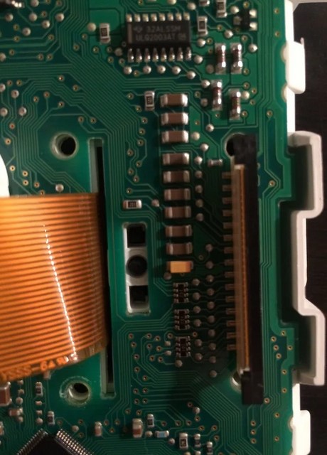
With the torex screws removed, lift the small black tab holding the ribbon in place, and remove the ribbon from it's holder.
Behind the ribbon, you will find a small black prong holding the center piece in place. Use your needle nose pliers (or anything that fits in here) to squeeze the prongs together.
Once you squeeze the prongs together, you should just be able to pull the center piece off of the board.
Step 3:
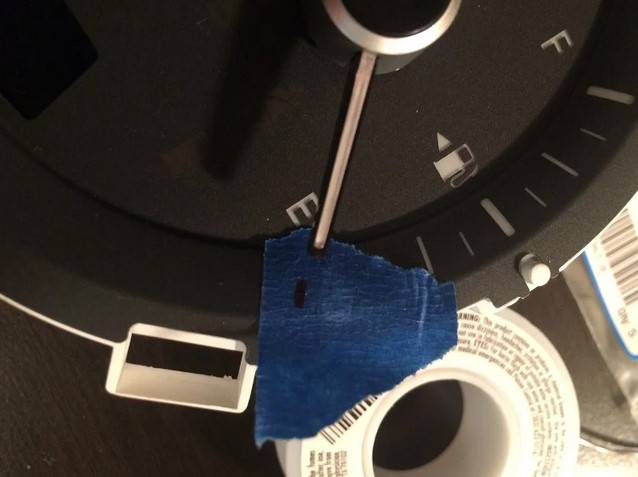
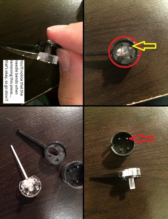
Next, you'll prep the front face for needle removal. Really, all we are gonna do is mark the placement of the needles.
Make sure that the needles are in their resting position - either lift the gauges up in a normal position (like they are placed in your car), and allow the needles to rest, or slightly move the needle manually. Be careful to not push the needle too hard - the needles should spin pretty easy unless they are at the resting point (you'll feel it if it's gone too far).
Mark the placement with some tape, or a slight tick mark on the face plate itself (out of view when placed in the car, of course). I did the later, but I have done it with tape as well, just so you get the idea.
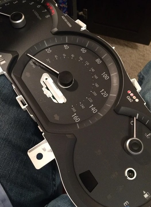
Step 4:
Now it's time to remove the needles. I HIGHLY recommend using two flat head objects (screwdrivers, butter knives, anything that will give leverage and is flat) to do this. I DO NOT recommend pliers, as you want to get an even lift on the needle base, without bending the pin or the motor it's attached to.
Simply place the flat objects under the needle (one flat object on each side, directly across from each other), and apply pry the needle upward. Remember to apply leverage equally on each side. Don't worry, you will have to give it a little pressure, and the needle should just pop off.
Step 5a (Needle Change Only):
At this time, it may be best to go ahead and work on the needles. The only reason to do this now, rather than at the end, is because you will need to let the needles dry before placing them back on the board. If you want to keep red needles, you can skip this step.
If you look at the back of the needles, you will see 4 pin type objects. With your x-acto knife, or razor blade, you will need to cut these off. Once the pins are sufficiently cut, you will be able to remove the needle from the housing. This may take a while, but be patient and it'll come. Next, you will need to remove backing - follow the picture on how to do this.
Remove the paint on the back of the needle with either nail polish remover, or your razor blade (don't cut or "fillet" the paint off, but rather etch it off by dragging the razor blade's vertical edge along the needle's horizontal surface). Once all the paint is removed, allow to dry (if using nail polish remover), then paint on a thin coat of just white using your paint brush or q-tip.
Step 5b (Needle Change Only):
After the paint is dry, repeat step 5a in reverse and place the needles back together. Once the needles are back together, cover the 4 pin objects with some of your clear glue. I used rubber cement, but that's only because I had it. Super glue, or any other clear, extra hold, glue will suffice.
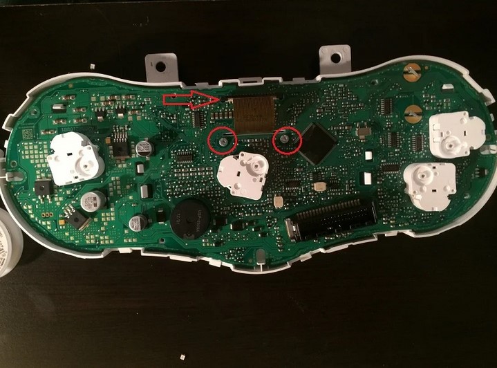
Step 6:
Remove the face plate and you'll see that you can't quite remove the circuit board yet because it's being held in place by the transmission indicator. To remove the indicator, you'll need to remove the brace. Turn the board over and you'll see two pieces that need to be turned. Grab your pliers and twist them so they line up with the holes behind them. Then push the brace through the board.
With this brace removed, the indicator should be easy to remove. Behind the indicator is a clear diffuser... you probably don't want to lose that.
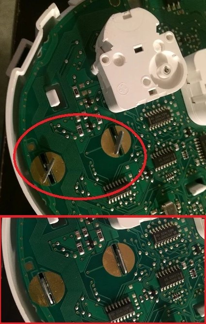
Step 7:
Ah! Glorious (and tiny) LEDs! Notice the difference between the PLCC4 and PLCC2 (PLCC4 has four prongs, PLCC2 has two... easy enough). Also, notice that one corner of each LED has a small triangle cut out. This shows you which way the LED should be placed on the board.
Go ahead and start removing the LEDs that you want to change, and replacing them with the colors you want. You can remove and replace one at a time, or do them all at once. Just remember to take note of the original position! Removal of the LEDs does take a little finesse, and the exact method is all based on user preference. You can desolder with a wick or wires braid, or you can even use a vacuum pump to remove the solder. I use neither - instead, I simply heat up one side and kind of lift the heated side with the iron (with a slight flick). You can also lift the heated side with tweezers. Totally up to you.
Step 8 (Needle Change Only):
This step is a little hard to explain, but I'm going to do my best without confusing anyone.
Around each needle pin, you will see PLCC4 LEDs. The tachometer and speedometer have four, where the temp and fuel only have two. You will notice that the speedometer LEDs have greater spacing between them than any other pin. This helps with the color change.
Look at the back of the needle - you will see a clear spot through the backing. This allows the needle to light up in the color of the LED which the clear spot is hovering over. So, if you are going 5 MPH, and the LED at that location is blue, the needle will be blue. If you are going 80 MPH and the LED is red, the needle will be red. You get the picture. The problem with the tach, fuel, and temp needles is that they are so close together that the colors blend rather than distinguishing between colors. To get these needles to change color, the LED MUST be elevated off the board somehow, or there must be some kind of divider placed between the two differentiating LEDs. Maybe you use metal picks, or some sturdy metal wire. Maybe you even use solder "legs". However you do it, just make sure that the contacts don't touch each other.
To be safe, I suggest sticking to solid colors on all needles except the speedometer (FYI - I tried to do green for full, and red for empty... I got orange. So I changed it all to green for my "go-go" juice :rolleyes:).
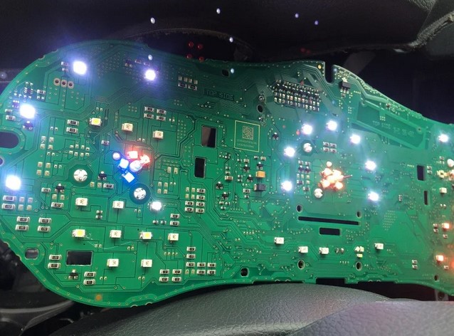
Step 9:
Testing time! Go back out to your car, plug in the board, turn on the car and see what happens. If all went well, the lights should light up. Don't worry about the needles or anything else just yet.
Step 10:
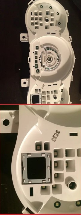
It's time to move onto the face plate.
On the back of the face plate, cover the areas you want to change color with the translucent film. Test by placing the face plate up to a light.
Step 11:
With everything tested, it's time to start putting the gauges back together. Put the board back in the housing, place the transmission indicator back in place (don't forget the white diffuser), then place the indicator brace back in. Be sure to twist the backs of the brace back in place.
Story’s Author
 United States of America, Arkansas