Here's my DIY tutorial for replacing the maplight LEDs in the overhead console.
Unlike most of the lights in the car, these LEDs are soldered onto a circuit board and aren't easily replaced like a typical bulb.
If you're like me and you've swapped all the other interior bulbs with nice LED's , you'll notice how dim and yellow the factory LED maplights are. This swap will complete the interior lighting to all white LED's , will be brighter than stock and just make things more cosmetically pleasing.
I was able to complete this swap in about 2 hours without any prior experience working with circuit boards.
This job requires complete removal of the overhead console, disassembly of the console to remove the circuit board, removal and replacement of the 4 surface mounted LED chips from the board, and re-assembly.
Tools and Supplies
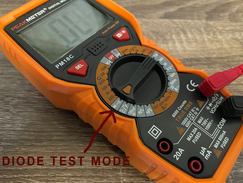
Multi-meter with Diode Test mode
Large body panel removal tool with angled head
Small body panel removal tool with sharp edge
Torx T20 screwdriver
Butane soldering torch with hot air blow tip
Flux
Toothpick
Isopropyl acohol
Q-tip
Soldering paste
IMPORTANT: a clean work area so you don't contaminate the chips or circuit board.
OPTIONAL
Soldering helping hands (Third hand) or circuit board holder
Fan
Duster spray
Electronics cleaner
Step 1 SMD LED chip testing
Use your multi-meter in Diode Test mode to test the new LED chips prior to mounting them on the board.
This ensures they work and also identifies the positive and negative side of the chip. Since LEDs are directional diodes they need to be mounted in the correct orientation to function.
In Diode Test mode, place the probes on the terminals on each side and the multi-meter will send a low current and the LED lights up. It will be dimly lit so don't worry about that. Swap the probes if it's not working. Make note of positive/negative side. On the units I received the negative side had a disctinct dark spot on them, barely noticeable.
Step 2 Overhead Console Removal.
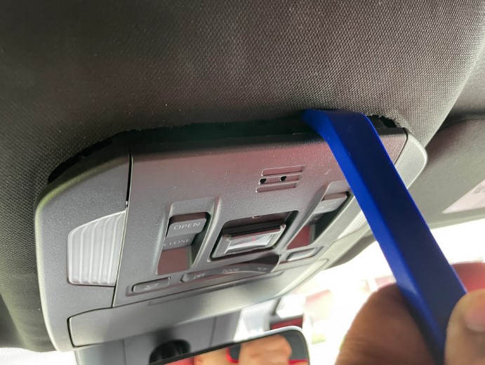
Use the large body panel removal tool to release the 4 retaining clips. The circles in the photo show their approximate locations.
Start at the top left, then top right. Squeeze the tool in until the bend part of the tool, then use the angled head on the tool as leverage to push the console down, releasing the clip.
Then pull the lower portion straight down with two hands and it should release the 2 lower clips .
Unplug the harness connector by pushing the tab in the middle.
Tape up the connector plug to prevent damage.
Take it to your clean work area
Step 3 Console Disassembly
Next we need to take the console apart.
The orange circles in the photo above show approximate locations I pryed at to release the trim pieces.
Remove the middle trim containing the buttons first. Use the small body panel removal tool to pry and release the Y clips.
A tool with a thin fine edge would be a huge advantage here.
Release the edge just below the sunroof buttons first, then pry the sides then along the edge next to the sunglass holder door.
The Y clips are brittle and crack easily, I broke a few at the tips which doesn't seem to effect their function. As long you don't break them off at their base you should be ok.
Next remove the surrounding trim. Do not remove the sunglass holder. This doesn't need to be disassembled.
Pry next to each Y clip along the outer edge until it's fully released.
Set these trim pieces aside.
Step 4 Circuit Board Removal.
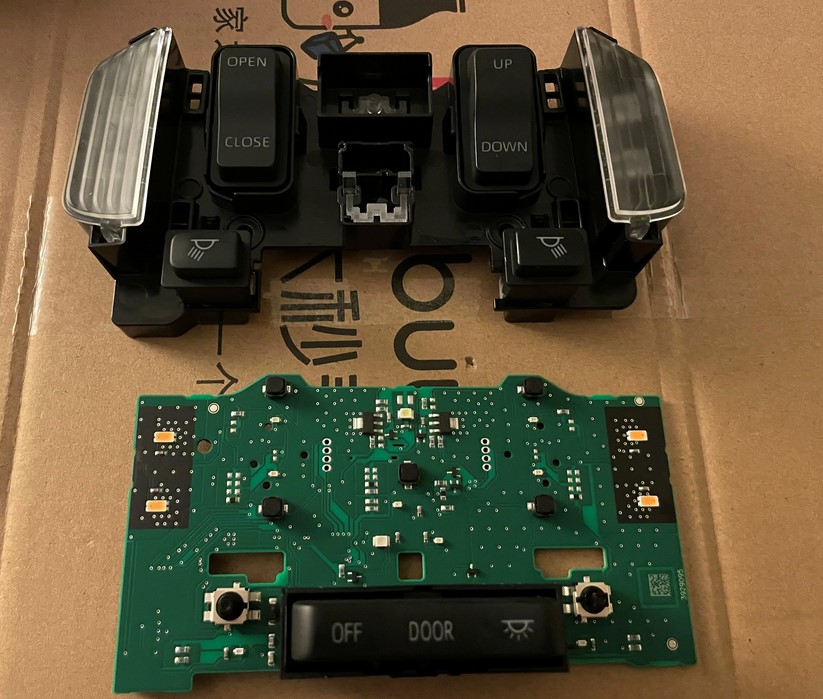
Next locate the 2 torx screws and remove them with your torx T20 screwdriver.
Just pull straight up to remove, the circuit board/button assembly comes out together.
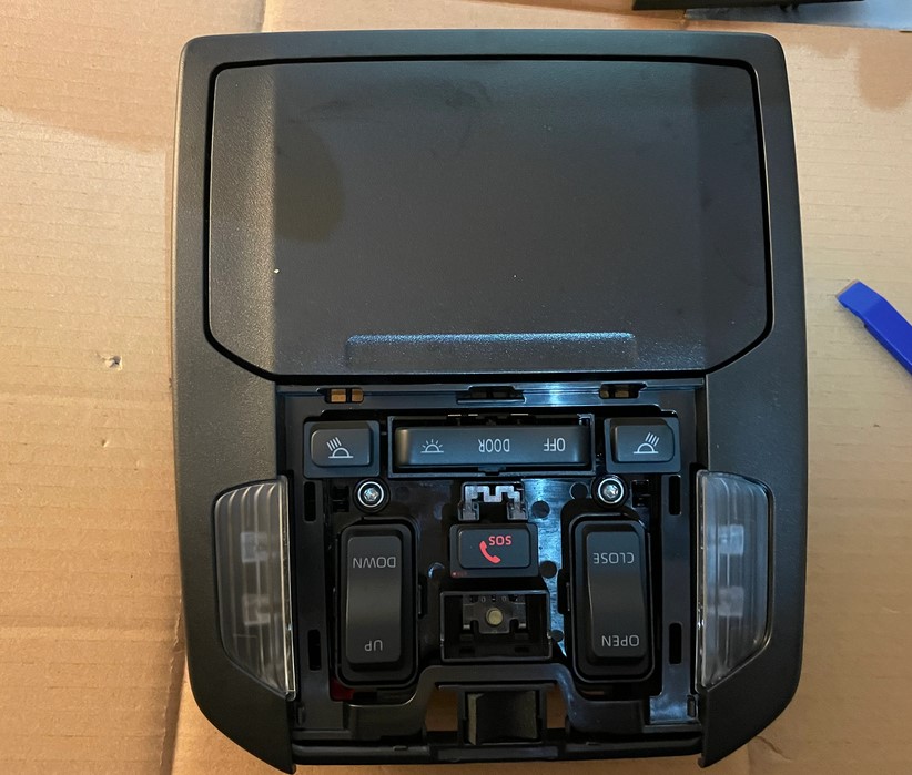
Next we need to separate the circuit board from the button assembly.
This took a while to figure out, there's a few switches and the 2 lens on the side , seems like a lot going on here but the board is only attached to its button assembly at the 2 map light switches.
Just pull up at each maplight switch to release the button assembly from the board. See photo above.
The LED chips are now visible.
The harness connector is part of this board so make sure it is still taped up to prevent damage to the connector pins.
Step 5 Identify Stock LED Orientation
The photo above shows the positive and negative side of each LED chip on the board, as noted previously you will need the correct orientation of the chip or the LED won't work.
Same as with the LED testing above, I used the Diode Test mode on the multi-meter, placed the probes on the stock LED chip terminals to find the positive and negative sides.
Step 6 Remove Stock LEDs
I was not able to take photos and do these next steps at the same time so I'll try to explain it clearly.
Apply flux with a toothpick around each LED, this will help soften the solder under the chips.
I'm using rosin paste flux which I keep around the house for various soldering jobs in my vehicles and hobbies.
They sell flux in liquid form in pens or syringes which are easier to apply. Digikey also carries these so grab some when you buy the LEDs.
You'll need your butane torch with hot air blow tip now. To remove the LEDs, apply heat to the OTHER side of the board, directly behind each LED.
Use a helping hand tool or circuit board holder to secure the board or find some other way to prop/hold the board firmly while having both sides accessible.
Let the torch heat up good then apply heat in a tight circular motion behind the LED, don't stop moving it, making sure not to go within an inch or 2 of the board.
The flux will smoke so use a fan to dissipate the chemical smell. As the solder softens use the tweezer to pull the chip off the board.
This shouldn't take very long, maybe 5-15 seconds or so depending on the strength of the torch.
With all the chips now off, use the alcohol and Qtip to clean up the mounting surfaces.
There will be old solder still there which I didn't remove.
Step 7 Solder New LEDs
The method I used to solder the new chips on requires no conventional soldering.
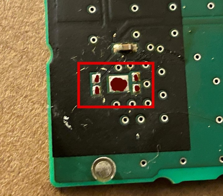
Apply the solder paste to the mounting surface parts marked in dark red in the photo above. This paste has a low melting point and sets quickly. Apply liberally and don't worry if you make a little mess but don't over do it. When heated the premixed flux in the paste will liquefy then burn off and the solids will pull together and bond the mating surfaces/old solder with new LED terminals.
I couldn't get a clear pic but I found one on google showing solder paste applied to various sized surfaces.
Place the new LED chip on top of the solder paste using the tweezers, remember orientation is important! Position the chip onto the mounting points. Use the tweezer to nudge into position. The solder paste is sticky and helps hold it in place.
Same as the removal process above, use the torch with the hot air tip to heat the OTHER side in a circular pattern, non-stop, making sure not to go within an inch or 2 of the board.
DO NOT HEAT THE LED DIRECTLY, THEY WILL DAMAGE.
After about 10 seconds it will start to bubble and smoke. Heat it for another couple seconds and let cool for a few seconds then try grabbing the chip with the tweezers making sure it's holding nice and solid.
Clean area around the chip with alcohol/Q-tip.
I did all 4 chips then plugged just the circuit board back into the map light harness hanging from the overhead console opening , make sure the switch is set to "DOOR" or "ON" and see if it works.
If it's not BAF then you screwed up somewhere and will need to start over. It should be incredibly bright with just the board plugged in and LED's completely exposed. The factory lens covers have diffusers in them covering each LED chip , which dramatically reduces the intensity.
If you want it blindingly bright, now would be a good time to remove/modify the diffusers to allow more light through.
Before doing this on my expensive Toyota circuit board, I practised on a circuit board from an old junk computer I had lying around.
Different types of SMD components can be soldered/desoldered using this method. Do it a bunch of times to various SMD components on a junk board until you're comfortable.
Step 8 Re-assemble Overhead Console.
With all the lights working you can now re-assemble everything by reverse procedure.
The only thing that took me a bit of time was figuring out how the board re-attaches to the button assembly.