Hey all, here is a guide to add full digital OnStar to your vehicle, and even tips on upgrading. I decided to move everything from my thread about me upgrading to new topics to make them easier to view and search.... The old post will be deleted and have a reference to my new posts instead....
What you'll need is a GMLAN generation 2 based VCIM (OnStar version 7.0 and above made after 2006), an antenna module foot from another Theta platform vehicle that had OnStar as well as the interconnect cable from rear to front for voice, data, and GPS, the mirror, dome light cover with microphone, and wire harness length from at least the mirror to the rear quarter panel, a wiring harness with long enough wires on it (suggest an Impala harness due to length), a connection cable from module to antenna interconnect, and some extra wire for extensions (suggests CAT5 cable and 2 wire with shielded audio cable.
Please remember to solder and tape all of your connections. DO NOT USE WIRING CONNECTORS. You will need to either add up to 3 wires to you radio's current wire harness (if your vehicle did not come equipped with OnStar) , or, purchase a splice harness that can also allow to add an amplifier without damaging your original factory radio wiring. I suggest the harness from iSimple known as PGHGM1. This harness has every connection and wire in it. Just remember to cut off the plug that runs into an iSimple device and to bridge the wires together that it connects in between by lining up the male and female plug ends. You'll have to add 3 more wires to your radio's wire harness if you are upgrading to a Navigation or MyLink radio
If using the wiring from an Impala, there is a terminator resistor in the wiring from the small plug and it will make it look like that there is more that one data-bus plain tan wire coming from it. Remove that resistor, or, DO NOT CONNECT IT. This resistor will cut off the data bus at the OnStar module.
As for the mirror, any OnStar mirror made after 2006 without map lights will work. Try pulling the mirror and wiring from a 2007 or newer Saturn VUE. They usually came with the compass, temperature, and auto-dimming mirror, however, you may want to run a separate temperature sensor for it. Pull the wiring as well all the way to the rear quarter panel of the vehicle. You do not need to pull the entire cable, just run this cable down the inside of the driver's side front window pillar and into the dash to where the OnStar Module is to be located.
The antenna comes in 3 parts. Pull the entire interconnect double coaxial line antenna cable from another Theta platform vehicle rear to front on the passenger side. Preferably one with the double connector on the dash to receiver end and the triple connector on the antenna end. You'll also want to remove either the entire antenna or just the base. Take note that if the base has a larger antenna screw in socket, you'll have to de-solder the socket/cap from your old base and solder it into this one. You also may want to find a base/Antenna with all connections built in like AM/FM, XM, Navigation, and OnStar inside. If the base is missing something like the XM antenna, you'll have to take both your old base and new base apart and install the antenna into the new base. When installing the interconnect cable, run it down the driver's side for easier access to the VCIM. You may not be able to pull the interconnect to receiver part of the cable connecting to the VCIM from the double connector. You may have to pull it from another vehicle such as an Impala. If not able to, pull out as much as you can from a Theta and cut it, and solder splice it with the antenna cables you pulled from and cut from another vehicle to the VCIM.
Now we're ready for actual installation of the wiring:
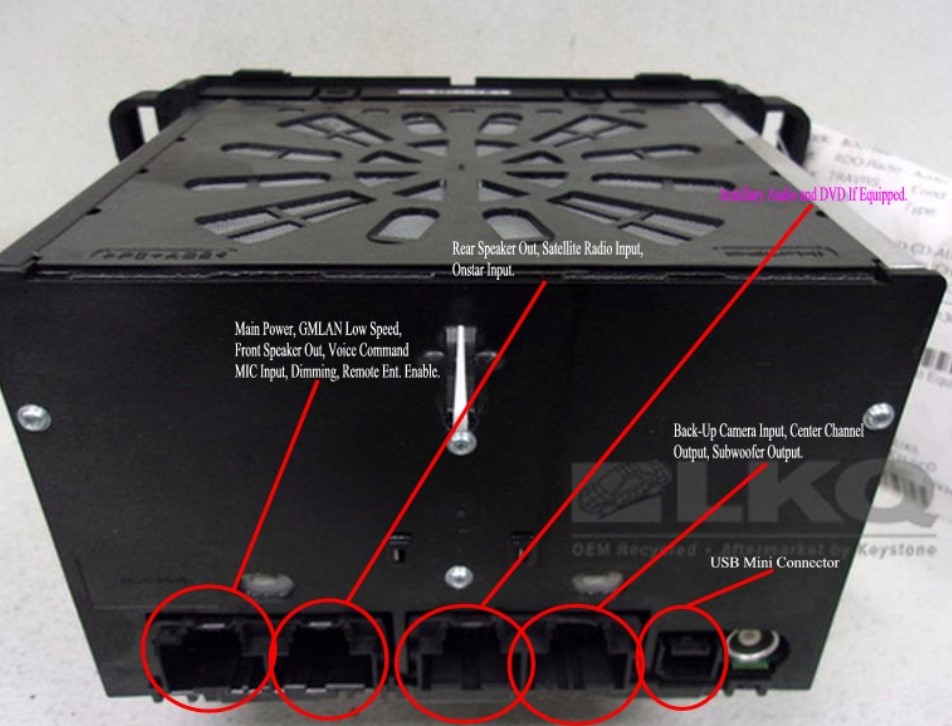
From the Module:
Red/White wire is main power positive. If you want to connect this as actual OnStar power from the OnStar fuse in the block in the center console, you may have to remove and take apart the fuse block and add a wire to the trace from the OnStar Fuse location. This trace should have a hole in it where a thin wire can be put through to it from the other side, and soldered into place. The black wire is the ground of course. You may also tie this in with the ground wire from the mirror and connect them to another ground wire connected in the vehicle.
The large black plug on the OnStar VCIM has Tan and Tan/Black GMLAN high speed wires. Connect those to the Tan and Tan/Black wires on the Body control module in the blue plug between the black and the white plug. If you have a BCM where both sets of GMLAN high speed wires in Tan and Tan/Black, these wires go into the upper ones in pins 8 and 9 on that BCM.
The small white plug on the OnStar VCIM may have either Brown and Brown/Black or Tan and Tan/Black wires. These connect to the other 2 wires similar in color on the BCM in that same blue plug.
Both sets of lines are actually connected as a module pass through, so, only the first set of lines might be required to be connected to retrieve data, however, it is always better to connect both sets and get a better data signal.
The dark green wire connects to the dark green wire in that same blue plug on the BCM.
When connecting the data wires, as suggested above, use CAT5 networking cable as an extension so that you have all the wires you need to connect all data channels, plus, connect the auto un-dimming mirror function as well if the mirror is equipped with auto-dimming.
Your data and power to the VCIM should now be connected, now, onto the mirror:
A basic mirror will have a yellow accessory power wire at which I suggest connecting to the RAP relay output on the fuse block, and, of course, a black ground wire.
Only 4 wires actually connect directly from the VCIM to the mirror and those are:
Dark Green/White (pin 11 on the mirror plug) is keypad signal.
Light Green/Black (pin 12) is keypad supply voltage.
Yellow/Black (pin 14) is the Green LED signal.
Brown/White (pin 15) is the red LED signal.
These wires all connect to the corresponding wires on the large black plug of the VCIM.
Microphone wiring should also be in this same harness:
Grey and a Bare wire usually wrapped in a shielded sheath and connects to the small white plug of the VCIM.
If you have a mirror with integrated compass and auto dimming:
Light Green (pin 9) is reverse lamp supply voltage. This auto undims your mirror when going into reverse. It connects to the Light Green wire of the pink plug between the brown and the grey plug on the BCM.
Light Green/Black (pin 6) is Ambient Temperature Sensor Signal positive. Make sure you identify this wire separately from the similar color wire for OnStar operation.
Grey (pin 7) is Ambient Temperature Sensor low reference.
Now, onto the audio wiring:
If connecting to a standard radio, you need to connect just 3 wires from the small plug of the VCIM to plug 2 of the radio:
Orange/Black is the OnStar left audio signal wire that connects to the rear speaker out radio plug in pin 7.
Light Blue is the OnStar left audio low reference wire that connects to the same plug on the radio at pin 15.
The Bare drain wire connects to the same radio plug at pin 11.
At this point, plug in everything and test your OnStar system by either hitting the phone button on the mirror, or, the Blue OnStar button once. The flashing light should be green if everything is connected properly and you should hear the automated prompts.
Now, for radios with MyLink/Navigation/Voice command capabilities, they use a grey plug that plugs into the black port of the OnStar Module to use OnStar's Microphone with the following 3 wires:
Pink is the Voice Recognition Audio Signal wire that connects to the Front speaker out (plug 1) radio plug in pin 4.
Pink/Black is the Voice Recognition low reference wire that connects to the same radio plug at pin 5. In some cases, this wire may also be grey and black.
The Bare drain wire also connects to the same radio plug at pin 11.
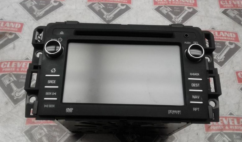
Here is a description of each and every radio pin:
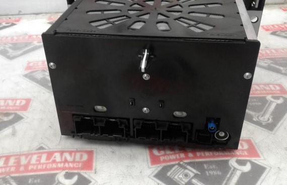
Now, there is full description at how to connect the OnStar module. When mounting it, the bracket from any Theta platform vehicle works perfectly.
Activation:
For activation, depending on route you take, if you want to do a self-activation, you will need the following:
A GM MDI clone for around $130 to $200 online (hint: do not look to eBay, look to other shops online), you can program it and activate it yourself using a 2 day $55 GM SPS subscription from here
Self-activation without a dealer involves using an MDI and a 2 day SPS subscription, however, this type of activation does not change the VIN on the cellular telephone account or associate it with your vehicle, so, you'll have to advise OnStar on the actual VIN of your vehicle and other info. When you run the activation from the SPS program, it will tell you that automatic activation was not successful, and you have to call OnStar to finish. When you close that popup, you'll see a screen advising you to wait 24 hours for activation to complete... Actually wait 48 hours, then push the blue OnStar button twice. Tell the system that you have never had OnStar in that vehicle and you'll be taken to new activations.. and you'll get 3 months free. You'll have to advise them that the module is in a different vehicle than what is being reported by the system, and, they can somewhat correct it on their end.
Dealing with VIN Mismatch:
VIN Mismatch happens when you try to activate with a representative that does not know what they are doing....
If your OnStar system has a red LED after activation, it's actually indicating a trouble code or codes in the OnStar module itself. To find out what is exactly causing the issue, and, to clear the trouble codes, you have to either have a Tech2 scan tool, or, an MDI and Tech2Win.
There is a program to correct the VIN associated with a newer OnStar Module with Bluetooth and have it matched to your vehicle. This matched VIN, but, new STID can appear as a brand new module to OnStar/GM and as a replacement, however, if you want it to appear as a New activation as well, perform the SPS steps as well once you have the module returned to you and installed.
Another thing the above program can do is clear your old module (even if it was an FMV) from your OnStar account and VIN, which, it appears OnStar reps cannot seem to at all.
After further research, found that the program or system used to match an OnStar module STID to a VIN is actually TIS2Web. Something that GM dealer shops are supposed to have access to, but, don't use it that often (or, may not know how).
Activation issues:
The most common and plaguing activation issue is Call-Drop during the process. This is NOT due to a VIN mismatch as it is more due to signal quality before the system is activated fully, especially if the module you installed has an MEID or ESN (Sprint Network) as opposed to an IMEI (AT&T Network). Before activation, these units only get a signal of 2 bars for voice and light data communication, plus, the early modules are only 3G capable at the most.
It's the same thing as activating a prepaid phone manually such as Boost Mobile (Sprint) and it may take several pushes of that OnStar button to complete activation. Once activated, your module will work as normal.
Activation through a dealer is similar, except that it costs $134, however, they will key your OnStar Account and module STID to your VIN in the process, and, you may not have to wait 48 hours and will not have to deal with call drops during activation.
I will be adding pictures of the wiring to this same post once I have completed it myself. Still working on getting the voice command connection from OnStar to the radio.
I hope this helps some.